Thursday, July 23, 2020

Mikrotik SMS Send Error no such channel (6)

One of the many features of Mikrotik router is, to send SMS using GSM modem. Using this feature, we can send notifications of any event in the form of SMS to the user's mobile phone.


In today's tutorial, we will discuss an error message that many users get when sending SMS. The error notification is: -

Couldn’t perform action – no such channel (6)

Here is a screenshot of this error notification:


Mikrotik communicates with the modem using a specific channel and sends SMS through that channel. The user has to specify this channel number while sending SMS. If for some reason the mikrotik router cannot communicate with that channel, then this error notification is shown. Many users make a mistake in entering this channel number. Here, they assign the channel number of the USB port. One thing to note here is that , even though we select the modem's USB as the port when sending SMS, but the router basically uses the serial port channel number as SMS sending channel. Does not use channel number of USB port. So when we assign the channel number of the USB port, the router fails to send an SMS using that channel and shows the error message.

So the solution to this problem is, we have to use the channel number of the serial port. We will select USB as the port and assign the number for the channel of the serial port.


We can find out the channel number of a port from the "port list".


And we will get access to “Port List” from “System - Port” location.


After giving the correct channel, I hope it will not show any error notification.


Wednesday, July 22, 2020

Mikrotik GRE Tunnel Configuration

In this tutorial, we will discuss how to configure GRE tunnel in Mikoritk Router. The GRE is a one kind of tunneling protocol. This protocol was developed by Cisco System. We can also call it communication protocol. This protocol is used to transfer data privately through public networks. This protocol creates a tunnel with two or more networking devices. Later, data will be sent using that tunnel. This tunnel can be point to point or point to multi point. At the end of this tutorial, we will learn how to establish a GRE tunnel between two Mikrotik routers. And how to transfer data using that tunnel. So let's get started:

We assume we have two site offices. Their names are Site-Office 1 and Site-Office 2. The two site offices have internal LAN network and both the offices are connected to the Internet. We further assume that the private network address of Site Office 1 is 10.10.10.0/24 and the public IP address is 1.1.1.1. Similarly, the private network address of Site Office 2 is 192.17.1.0/24 and the public IP address is 2.2.2.2. Now we will build a connection between these two networks using the GRE tunnel.

First we will create a tunnel using the public addresses of the two offices. We are starting the work of making tunnel from site office 1.

We will create a tunnel in the “GRE Tunnel” tab from the Interface menu.


We will click on the Add (+) button to create a new tunnel. Then the following interface will come in front of us.


In this interface we will provide the configuration of our tunnel. Here a name can be given for the tunnel interface in the “Name” field. In the “Local Address” field will be the public IP address of Site Office 1 i.e. 1.1.1.1. And in the “Remote Address” field will be the public IP address of Site Office 2 i.e. 2.2.2.2. I will apply and go out.


Tunnel configuration is over in our site office 1. Now we will create a tunnel in Site Office 2. The process of creating the tunnel here will be the same as the complete site office 1. Only the “Local Address” and “Remote Address” fields will change slightly. Here in the “Local Address” field will be the public IP address of Site Office 2 and in the “Remote Address” field will be the public IP address of Site Office 1.


After applying at the end of all configuration, our tunnel will go into running mode or will be activated. We can see the status of the tunnel at the bottom of this interface.


If the tunnel is not active then the text "running" will be blurred. If the tunnel is disabled, then "disabled" will be written. We have finished building the tunnel. Now we need to enable data transfer between the two offices using this tunnel. To enable this data transfer, we need to configure "IP route" between the two offices. And to configure “IP route” we have to assign IP address in the tunnel interface. We will give the IP address as 192.18.68.1/24 in the tunnel interface of Site Office 1 and 192.18.68.2/24 as the IP address in the tunnel interface of Site Office 2.

So, now let's configure the IP address. First I will give the IP address in the tunnel of site office 1. To configure the IP address, our location is:  IP -> Address


Now in this interface I will give the IP address in the “Address” field and select our tunnel interface in the “Interface” field. The name of our tunnel interface in Site Office 1 is "Site Office 1".


In the same way we will configure the IP address in Site Office 2. Our IP address at Site Office 2 will be 192.18.8.2/24.


Assigning IP address to our tunnel interface is done. Now we will configure the IP route between the two office routers. We will configure the route in the router of site office 1 for the local network of site office 2 i.e. for 192.18.1.0/24 network. And the gateway address for this will be the tunnel IP address of Site Office 2 i.e. 192.18.68.2. In the same way, we will configure the route to Site Office 2 for the local network of Site Office 1 i.e. 10.10.10.0/24 and its gateway address will be the tunnel IP address of Site Office 1 i.e. 192.18.68.1.

First let's start with the site office 1 router. Now, we will add a new route to the "Route List".


Now we will add route to site office 2.


All our work is over. From now on, the users of Site Office 1 will be able to access the network resource of Site Office 2 and at the same time the users of Site Office 2 will also be able to access the network resource of Site Office 1.


Mikrotik Connect USB Modem

Currently there are usb ports available in almost all mikrotik routers. Using this USB port we can connect USB storage or pen drive with mikrotik router. Again in the same way we can connect USB Modem. However, the modem must be mikrotik compatible. A list of modems that are compatible with mikrotik routers can be found at the link below.


In addition to the models mentioned in the list, it also supports almost all the modems available in the market. As we have used a simple modem in this tutorial, which is not in the compatible list of mikrotik. However, this modem supports by router. If a modem is compatible with the mikrotik router, then the router will show the information of that modem in its USB list, when the modem is connecting to the router,. It will also create a "PPP Client Apapter" for him. We used a modem from Qualcomm and it shows up in the middle of the list.


To view this USB list, we first go to System -> Resource. We can see this list by clicking on the USB button there.


In addition to showing in this list, the router will create a “PPP Client” adapter for our modem and show it in the PPP interface list. However, this interface will remain disabled.


If a modem does not automatically detect by router, then we must assume that, this modem is not mikrotik compatible.

Now we will open the adapter to connect the modem and provide the APN information of the modem.


This APN information can be obtained from the SIM operator. Another thing we need to note is, whether the modem port is automatically detected. If not, then we have to manually select it.


Then we go to "Advanced Mode". For that, you just have to click on the “Advanced Mode” button.


After accessing the “Advanced Mode” we will go to the “PPP” tab. There we have to enter a dial number in the “Phone” field. Usually the number is "* 99 #". The number may also change from country to country. You can get this number from SIM operators. However, in most countries the number is "* 99 #".


If you want to use the connection of this modem as secondary, then you have to increase the value of routing distance of this connection.

Suppose, we are connected to the internet in two ways. The first is broadband cable connection and the second is GSM Modem connection. Of course, modem connection will be much slower than cable connection. So we all want all the traffic on the internet to be forwarded with cable connection. If for some reason the cable connection is disconnected, then all traffic will be forwarded with the modem connection. To do this we will use the value of routing distance. The lower the value, the more the network will be counted first. The value next to it is second and the value after it is third, thus it will be given priority. In this scenario, the routing distance of broadband cable connection will be 1 and the value of routing distance of GSM modem connection will be 2. The value of this routing distance can be configured from the "Route Configuration" window.


In this tutorial, we have only used GSM modem for internet connection, so we are not changing the value of routing distance. That means there is 1.


After enabling and applying, the status of our adapter will change to "waiting for packets".


If everything is OK, after a while the status will be changed by "Link established" and then "connected".


At this stage our modem is now connected to the Internet. Now, to share this internet connection with users, we need to configure Source NAT using PPP client adapter. To configure NAT, we will go to “IP -> Firewall”. From there we will select “NAT”.


Now we will add a “src nat” rule by clicking on the “add (+)” button. Here we will select “srcnat” in the “Chain” field and have to select the PPP client adapter in the “Out Interface” field.


Now we will select "masquerade" as action.


Done. From now on all users will be able to connect to the internet using GSM modem.

Friday, July 17, 2020

ASA Firewall Enable ASDM on Interface

This is a step by step article. So every issue has been discussed in detail.

Firewall system, which can be used to ensure the best security of a network. Using it, we can monitor all types of services starting from access control in the network. For example, shutting down a particular service, applying an access restriction on a specific network, etc. We can easily implement all of these using firewall. These firewalls are usually of two types. One is software firewall and the other is hardware firewall. Notable among the hardware firewalls are: - Cisco ASA, Fortigate, Palo Alto, Barracuda, Sophos etc. In this article today we will discuss a feature of Cisco ASA Firewall.

There are two ways to access Cisco ASA Firewall. One is graphical access and the other is command line access. This graphical access is taken using HTTP protocol or Cisco ASDM tool. On the other hand, using the console port of the firewall, we can access the command line.

To get graphical access or ASDM access in the router, we must enable the HTTP protocol. The interface that we will use for ASDM access, we have to enable the HTTP protocol in that interface. By default, HTTP or ASDM access is enabled on the management port. So we can take ASDM access to that management port without any configuration.

But now if we want to get ASDM access using any interface other than that management interface, then we have to enable HTTP protocol for that interface. In this article, we will learn how to enable HTTP protocol in network interface. We can do this through two types of access. But if for some reason ASDM is not already enabled in any interface, then in that case we must do the work through command line access. Because in this case we have no way to take graphical access. So in this article we will discuss those two ways. One is ASDM access and the other is command line access.

Let us first discuss how to enable HTTP protocol in an interface using "Command Line Access".

In this tutorial, we have used “Putty” software for command line access. You can use any other terminal emulator program if you want. With access to the command line, we will go to "Global Configuration" mode. The command for that is “Config terminal”. Now your bash prompt will be like this:-


After accessing the “Global Configuration” mode, we will execute the following commands in stages.

http server enable

http 192.168.1.0 255.255.255.0 inside

Here The first command is, to enable HTTP server mode. And the second command is, to use the "Inside" interface to enable HTTP or ASDM access from the 192.16.1.0 network. If you want, you can enable access only for a specific IP without enabling access for the entire network. Then the command will be: -

http 192.168.1.1 255.255.255.255 inside

As example screenshot:-


According to this screenshot, HTTP or ASDM is enabled in all three interfaces. The first two are outside interface and the last one is inside interface. Here 0.0.0.0 means any IP address.

Now we can take graphical access using Cisco ASDM-IDM Launcher. We will gain access using the IP address or network address what we have allowed. Below is a screenshot:


If we do not have "Cisco ASDM-IDM" launcher installed, then we can install the software with http access through the browser. In this case we will open the browser and go to our allowed IP location. There we will get the option to install "Cisco ASDM-IDM" launcher. Below is a screenshot:


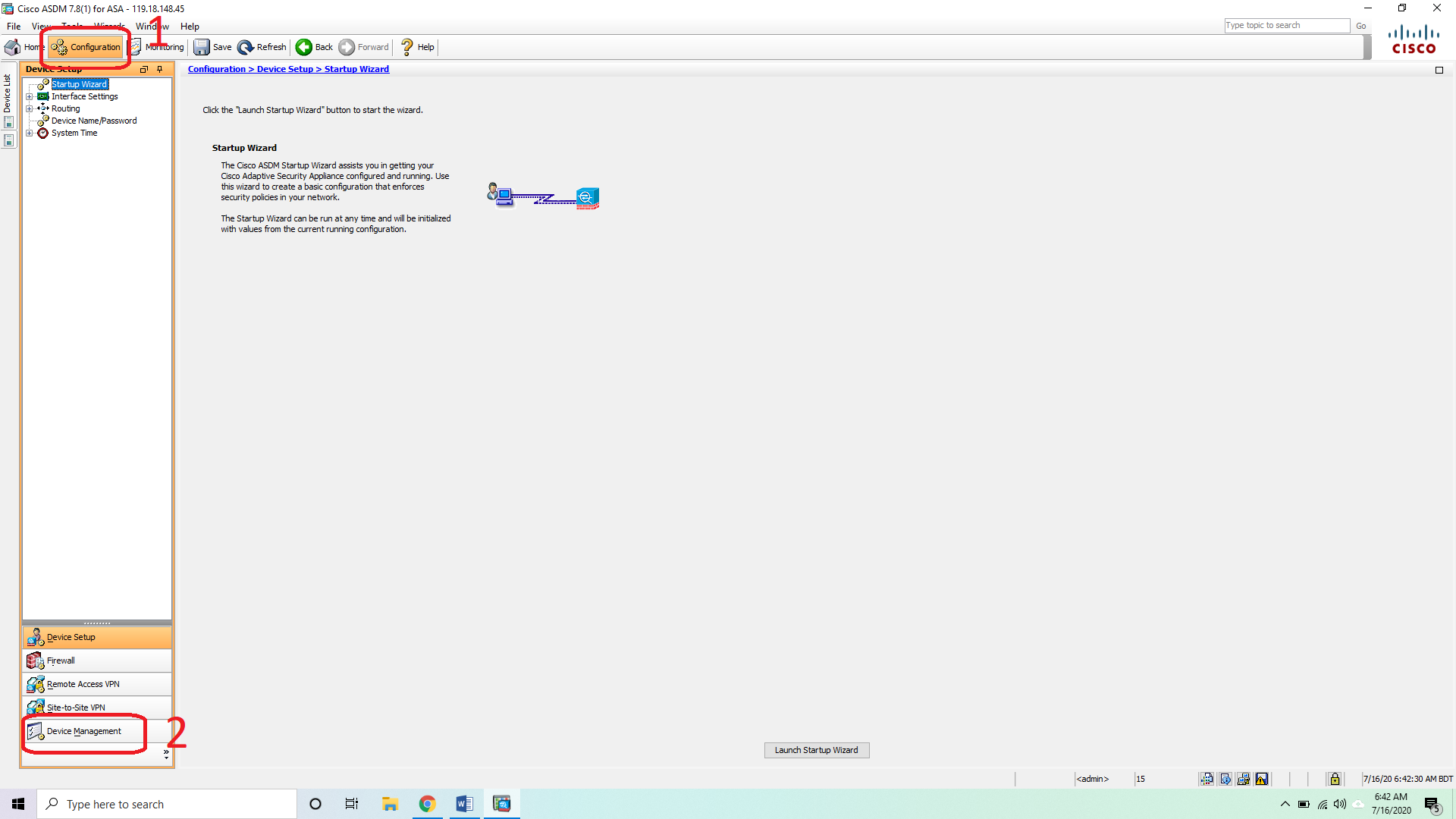
Let us discuss how to enable http protocol or http server in an interface using Cisco ASDM-IDM Launcher. After login using ASDM, we will go to the "Configuration" tab. Then we will select “Device Management” settings from the left panel.


Now we will expand “Management Access” from “Device Management” tree and select “ASDM / HTTPS / Telnet / SSH”.


Now we will click on the “Add” button to enable HTTP in the interface.


Here we will select our interface. Then I will write our IP address or network address and also write the subnet mask. We have used a specific IP address in our tutorial. That is why our subnet mask has been 255.255.255.255. This means that no part of this address will change. Precisely this address must be so. We have shown our "Inside" as the interface. Finally, I will close the interface by pressing "OK".


Yes, all our work is over. Now using this “inside” interface we can get HTTP access or ASDM access.