In this tutorial, we are going to learn the step-by-step process for the NAT configuration in the Cisco ASA firewall. We can use a firewall to connect to the internet as well as protect data from outside threats. A firewall can perform NAT functions like a router that is used to connect local users to the internet.
We know that we need to use one public IP address to connect to the internet. Because private IP addresses are not routable to the internet. That's why we share one public IP address or a range of public IP addresses among the LAN users. This is because it is very costly to provide separate public IP address to each other. To share one public IP address among so many users, we have to use NAT configurations. Using NAT, we can share one public IP address or we can share a range of public IP addresses.
In the Cisco ASA firewall, when we share one public IP address among the LAN users, then it is called "Dynamic PAT (Hide)". When we share a range of IP addresses then it is called "Dynamic NAT". If we want to allow access from the outside network to the inside network then we will use the “Static” NAT Method.
When the NAT configuration is done from the “Inside” interface to the “Outside” interface then it is called “Source NAT” and when it is done for “Outside” to “Inside” interface then it is called “Destination NAT”.
In this tutorial, we are going to configure both of the NAT functions. Generally, the source NAT is used to connect to the internet. For the source NAT configuration, we are going to share one public IP address among the LAN users. That's why we will use the "Dynamic PAT (Hide)" configuration. We will perform NAT function from inside interface to outside interface. All the LAN user's traffic that is intended to reach the internet or the outside network, their source address will be replaced by the outside interface IP address.
Source NAT
Now we will go through the step-by-step configuration process to perform the source NAT configuration in the Cisco ASA firewall.
We assume that we have a local network 192.168.1.0/24. Also, we have one public IP address 1.1.1.1. Now we are going to configure the NAT function so that our private IP address is translated to the public IP address. After that, we have to create one access list entry so that the firewall can allow the internet traffic from the inside interface to the outside interface.
At first, we will create a “network object NAT rule” for our LAN network. Then we will enable the NAT function on that network object.
To create a network object NAT rule, click on the “Firewall” option and then click on the “NAT” rules from the “Firewall” configuration page. Then click on the “Add” drop-down button and select the “Add Network Object NAT” rule.
Now we will give a descriptive name for this object. We will name it "NAT_Rule_Internet". Then select the object type from the drop-down list. Here, we will select "network" as the object type. Make sure that the "IPv4" radio button is selected as the "IP Version". Write your network address in the "IP Address" field. Here, we will write "192.168.1.0" as the network address. Because we are going to NAT this local address to our public address which is 1.1.1.1. Then write your subnet mask in the "Netmask" field. You can select a mask from the drop-down list also.
Now we will configure the source NAT. Please make sure that the "Add Automatic Address Translation Rules" check box is ticked in the "NAT" section. In the "Type" field, select "Dynamic PAT (Hide)" from the drop-down list. Now write your public IP address in the "Translated Addr" field which is 1.1.1.1 or you can select your public interface from the interface list. After that click on the "Advanced" tab.
In the "Advanced" tab, we will select the source NAT interface and the destination NAT interface. The source NAT interface is that which will be translated. And the destination NAT interface is one whose address will be used to translate the source interface.
Now select your "inside" interface or the LAN interface from the "Source Interface" field. Because we are going to translate the local private IP address to the public one. Then select your "outside" interface from the "Destination Interface" field. Then click on the "OK" button to close this window.
Finally, click on the "OK" button to save this network object NAT rule. Now click on the "Apply" button to save these changes into the "Running-config".
Our source NAT configuration process is done. One final thing we have to do that create an access rule to allow the traffic from inside to outside network. By default, the firewall blocks all the traffic from inside to outside interface and outside to inside interface also. We will create an access rule that allows all the traffic coming from the inside interface and intended to go to the outside network or the internet.
To create an access rule, go to the "Firewall" option and click on the "Access Rules" from the firewall configuration page. Then click on the "Add" button to add a new rule.
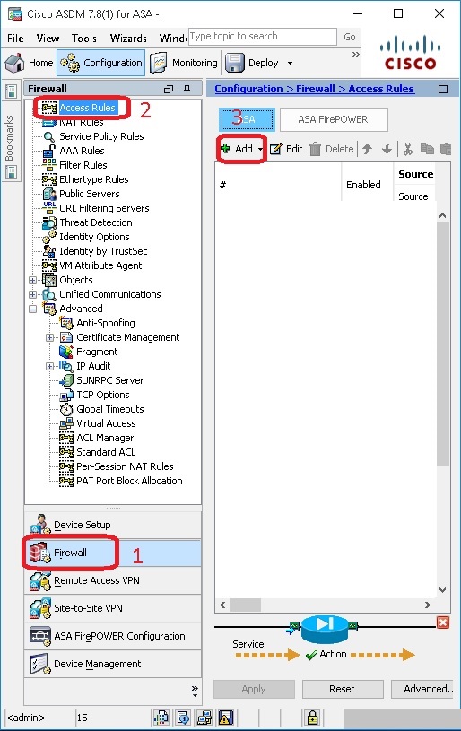
Now we will select the interface from the drop-down list on which we will deploy this ACL. Here, we will select the "outside" interface because we are going to apply this ACL in the outside interface. Click on the "Permit" radio button as the "Action" field value. Keep the default value in the source and destination field. Leave the default value for the "service" field also. Then expand the "More Options" feature.
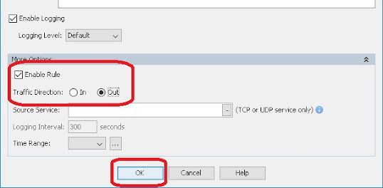
Here, make sure the "Enable Rule" tick button is ticked. Now click on the "Out" radio button as the "Traffic Direction" value. Because we create this ACL to allow the outgoing traffic from inside to the outside interface. After then click on "OK" to add this ACL into the "ACL List".
All the things are done. Now firewall will any traffic from inside to the outside interface coming from any source address. From now on all the local users can connect to the internet.
Destination NAT
Now we are going to configure the destination NAT process. Generally, the destination NAT is used to make available an internal LAN server over the internet. If we want to make accessible one of our internal servers to the internet and at the same time we don’t want to use any public IP on that server, in that case, we have to use the destination NAT function. After deploying the destination NAT, we can take access our internal LAN server from the internet using our outside interface IP address or our public IP address. We can forward a specific port number to our internal LAN server using this destination NAT process. With that port number when any traffic will come to our outside interface then that traffic will be sent to our internal LAN server using the same port number. This process is called port forwarding.
In this tutorial, we are going to forward the "FTP" port to my local FTP server using the ASDM tool. This will allow access to our local FTP server from the outside network. This is also called the destination NAT. We will go through the step-by-step process.
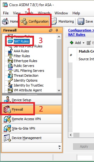
After login into the firewall using ASDM, we will go to the "Configuration" tab and then we will click on the "Firewall" button from the left panel. After click on the "Firewall" button, we will select "NAT Rules" from the "Firewall Configuration Page".
Now click on the "Add" drop-down menu button and select "Add Network Object NAT Rule".
Now write a name for this entry into the "Name" field. We named it "FTP_Traffic_Forward". Please note that we can't use space in the name field. Now select the "Host" value from the "Type" parameter. Write the local FTP server IP address in the "IP Address" field. We assume that our FTP server IP address is 192.168.1.10.
Now we have to be sure that the "Add Automatic Address Translation Rules" button is ticked. Select the "Static" value from the drop-down menu in the "Type" field. Select your "Outside" interface in the "Translated Addr" field. Here, the outside interface is representing your WAN interface. In this example, our outside interface name is "outside".
Now click on the "Advanced" button.
In the "Advanced" settings, select your inside interface in the "Source Interface" field. Here, the inside interface is representing your LAN interface and we assume that our inside interface name is "inside". Now select your outside interface in the "Destination Interface" field. Here, the outside interface is representing your WAN interface. Make sure the "TCP" value is selected in the "Protocol" field. Now write your FTP service port number in the "Real Port" as well as in the "Mapped Port". We know that the default FTP service port number is 21.
[Note:- Here, the Real port is representing our local server FTP port number that is 21 and the Mapped port is representing the port number that is used to connect to my outside interface or our real IP address. ]
That's it. All the work is done. After click on the "OK" button and "Apply" the configuration, the new rule will ready to be worked. To apply this setting in the "Running-Config" just click on the "Apply" button.
One more thing we have to do. The traffic has to be allowed by ACL also. By default firewall drop all the traffic that is coming through the Outside interface. That's why we have to create an access control list in the "Outside" interface so that the traffic is not going to block by the firewall.
To add an ACL in the "Outside" interface click on the "Access Rules" button from the firewall configuration page.
To add an access rule click on the add button.
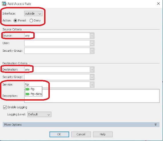
After opening the "Add Access Rule" window, select your outside interface from the "Interface" parameter. According to our scenario, our outside interface will be "Outside". Select the "Permit" radio button as we are going to allow the traffic through this ACL. For the "Source Criteria" and the "Destination Criteria" section, leave the default settings in the "Source" and "Destination" parameter boxes. As the default, the "Source" and "Destination" parameter values will be "any". After then click on the "Service" parameter box. Now write your service name that is "FTP" according to our scenario. During you enter the service name, you will be noticed that the list of the possible services is shown based on your keyword. Just select your desire one from that list.
After that click on the "More Options" drop-down button. Now click on the "In" radio button in the "Traffic Direction" parameter, since we are configuring the ACL to allow the traffic from outside networks that are intended to access our local network using the internet. Finally, click on "OK" to close this window.
From now on our local FTP server will be accessible from the internet. The firewall will allow all the traffic that is intended to go to the FTP server. This process is also called the "Destination NAT".


